


The KA3525 is a versatile pulse-width modulation (PWM) controller designed for high-efficiency DC-DC converters, inverters, and other power management applications. It integrates multiple functions into a single chip, including a voltage reference, error amplifier, and PWM control circuitry. The KA3525 is known for its flexibility, high performance, and ease of use in designing various switching power supplies.
Key Features:
- Integrated PWM control for efficient power conversion
- Adjustable output voltage for customizable applications
- Built-in voltage reference for stable operation
- Error amplifier for precise regulation
- Adjustable dead-time control for improved performance
- High-speed switching capability for efficient operation
- Multiple protection features including overcurrent and thermal protection
- Input Voltage Range: 7V to 40V
- Output Voltage Range: Adjustable, depending on external components
- Switching Frequency: Adjustable, typically up to 100 kHz
- Voltage Reference: 2.5V ±1% (typical)
- Error Amplifier Gain: 10 to 1000
- Dead-Time Control: Adjustable
- Thermal Shutdown: Integrated
- Overcurrent Protection: Integrated
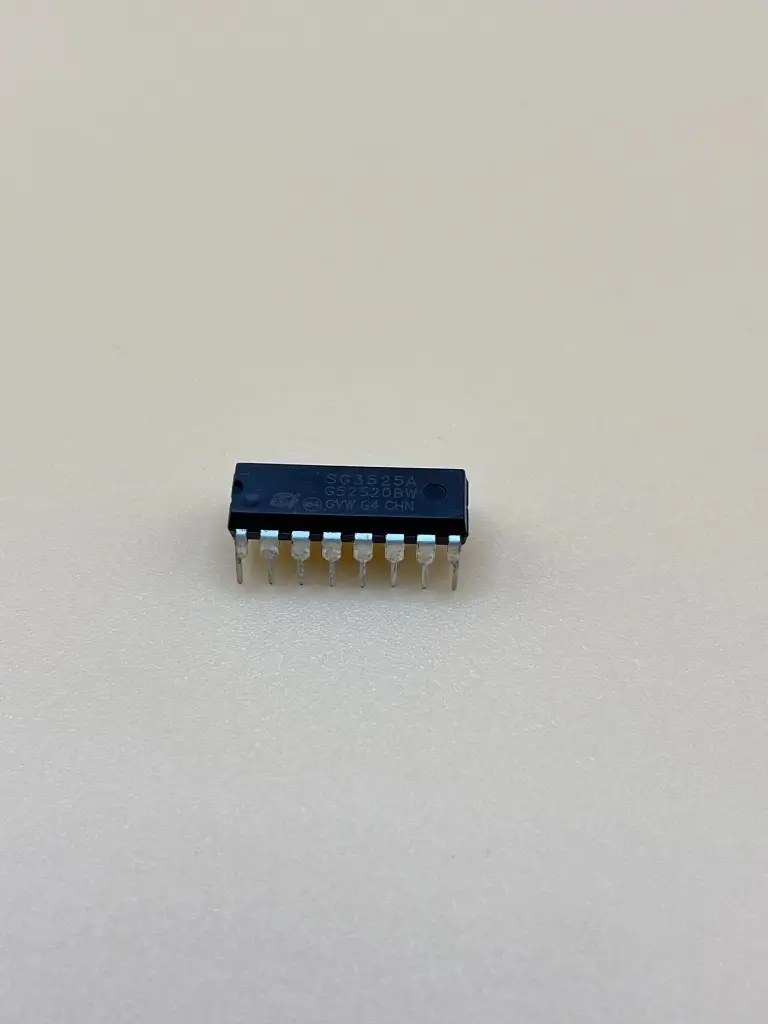
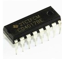
- Package Type: Typically available in DIP-16 and surface-mount packages
- DC-DC converters (buck, boost, and flyback)
- Power inverters for renewable energy systems
- Switching power supplies for electronic devices
- Battery chargers
- Motor control circuits
- High-efficiency power management systems
- Connect the input voltage to the appropriate pins of the KA3525, ensuring it is within the specified range.
- Configure the output voltage using external resistors and feedback network as specified in the datasheet.
- Set the switching frequency and dead-time control according to your application requirements.
- Connect the load to the output and ensure proper cooling and heat dissipation.
- Ensure that the input voltage is within the specified limits to avoid damage to the chip.
- Properly design the external components (e.g., inductors, capacitors) to achieve desired performance and stability.
- Implement thermal management and protection features to prevent overheating and ensure reliable operation.
No Specifications