Description
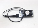
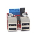
The Automatic Solar Tracker Module HD-36 is a single-axis light source tracking board designed to orient a solar panel or other device toward the brightest light source. The module operates by comparing light intensity between two photoresistor sensors. When a shadow falls on one sensor due to an obstruction (such as a small shade or the edge of a solar panel), the resulting imbalance in light intensity triggers a geared DC motor to rotate until both sensors receive equal illumination. This closed-loop feedback system continuously seeks the light source center, improving solar energy collection efficiency in photovoltaic systems. The compact PCB measures just 35mm × 16mm × 1.2mm and operates on a 5–5.5V DC power supply.
Key Features
- Single-axis solar tracking for following the sun's position across one plane (typically east to west)
- Uses two photoresistor sensors with an external shade to detect light intensity differences
- Controls a geared DC motor to rotate the solar panel toward the brightest light source
- Integrated anti-shake circuit with short delay prevents oscillation when aligned with light source
- Motor polarity reversible — swap wires if rotation direction is opposite to light source movement
- Compact board dimensions: 35mm × 16mm × 1.2mm for easy integration into solar tracking systems
- Low current consumption under 1.5A
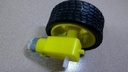
- Compatible with JGY370 6V geared motor (recommended by manufacturer for stable speed)
- Simple wiring with only power connections and motor output terminals
Specifications
- Product Name: Single-axis light source tracking board / HD-36 Solar Tracker Module
- Board Dimensions: 35mm × 16mm × 1.2mm
- Supply Voltage: 5V to 5.5V DC (regulated power supply required)
- Maximum Current: Less than 1.5A
- Motor Interface: Two-pin terminal (M+ / M-) — polarity reversible
- Power Interface: Power positive (+) and negative (-)
- Cable Length: 15cm (integrated wiring from module)
- Recommended Motor: JGY370 6V geared motor (slow speed type)
- Operating Principle: Photoresistor differential comparison using shade to create shadow imbalance
- Mounting: Photoresistor probes must be mounted on the same plane with a shared shade covering both sensors simultaneously
Wiring Instructions
- Power Supply: Connect a regulated DC power source providing 5V to 5.5V. Do not connect directly to a solar panel without a voltage regulator. Maximum current draw is under 1.5A.
- Motor Connection: Connect a geared DC motor to the M+ and M- terminals. The slower the motor speed, the better the tracking accuracy. The manufacturer recommends the JGY370 6V geared motor, which operates reliably at 5V under light load.
- Polarity Adjustment: The motor terminals are non-polarized. If the motor rotates away from the light source instead of toward it, simply swap the two motor wires.
- Anti-Shake Feature: The circuit includes a short delay mechanism that prevents the motor from oscillating left and right once it has aligned with the light source center.
- Voltage Regulation Warning: The power supply must be regulated to 5–5.5V DC. Direct connection to a solar panel (unregulated) may damage the module.
Applications
- Solar energy systems: Improves photovoltaic panel efficiency by keeping panels oriented toward the sun throughout the day
- Solar-powered working stations: Maintains optimal illumination for solar-powered equipment
- Educational projects: Demonstrates closed-loop control systems and light tracking principles
- DIY solar trackers: For hobbyists building single-axis solar tracking platforms
- Agricultural solar systems: Maximizes power generation for irrigation pumps and remote monitoring stations