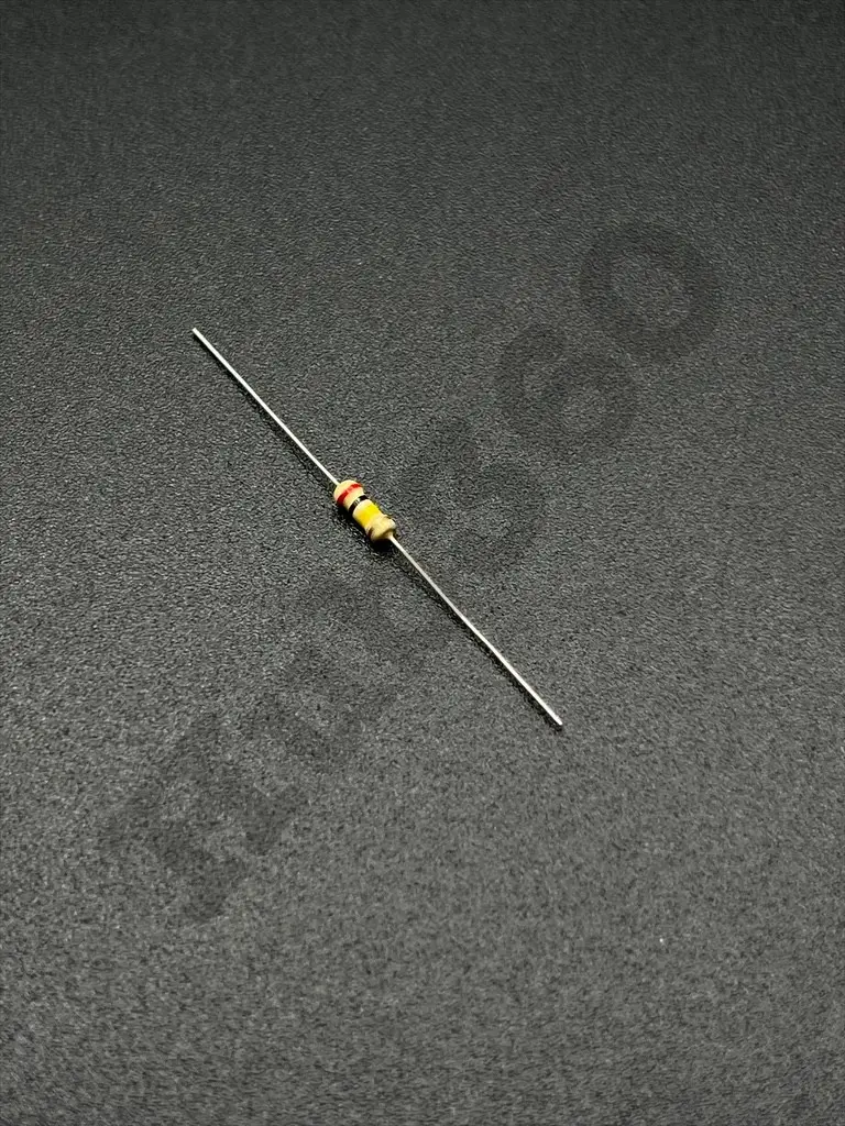
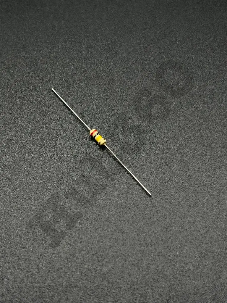
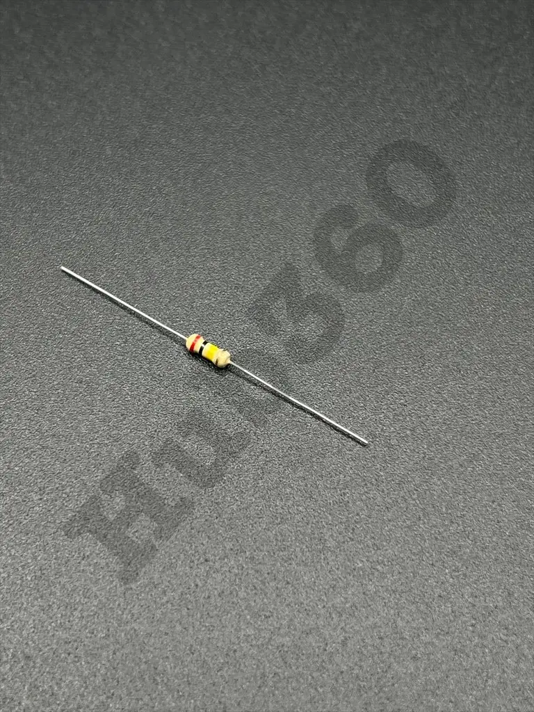
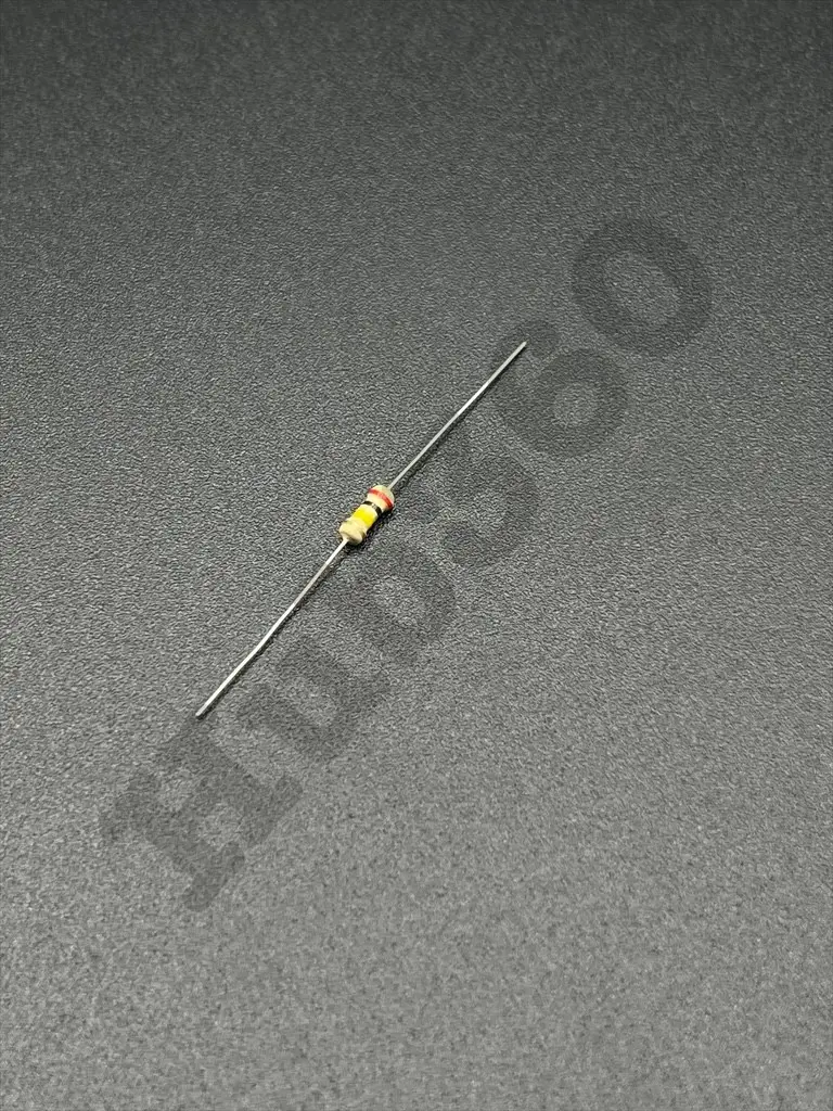

200KΩ 1/4W resistor
A 200KΩ (ohm) 1/4 watt resistor is a fixed resistor designed to provide a resistance value of 200,000 ohms with a power dissipation rating of 0.25 watts (1/4W). It is used in electronic circuits for tasks such as current limiting, voltage division, and setting bias points.
Key Features:
- Resistance: 200KΩ
- Power Rating: 1/4W (0.25 watts)
- Tolerance: ±5% (commonly), with ±1% available for precision types
- Temperature Coefficient: Typically ±100ppm/°C or ±200ppm/°C for general-purpose resistors
- Resistance: 200KΩ
- Power Rating: 1/4W (0.25 watts)
- Tolerance: ±5% (J), ±1% (F), depending on the specific resistor type
- Temperature Coefficient: ±100ppm/°C or ±200ppm/°C
- Operating Temperature Range: -55°C to +155°C
- Body Size: Typically through-hole with axial leads (1/4W size)
- Material: Carbon film, metal film, or metal oxide, depending on the type
- Current Limiting: Used to limit current flow and protect other components in a circuit.
- Voltage Division: Employed in voltage divider circuits to achieve desired voltage levels.
- Biasing: Used in circuits to set the operating points of transistors and other components.
- Signal Conditioning: Helps in adjusting signal levels in various electronic applications.
- Load Resistor: Acts as a load in electronic devices and circuits.
- Placement: Locate the resistor's position on the PCB.
- Insertion: Insert the resistor leads into the appropriate holes on the circuit board.
- Soldering: Solder the leads to the PCB pads and trim any excess leads.
- Verification: Check the resistance with a multimeter to ensure correct installation.
- Power Dissipation: Ensure the resistor does not exceed its 0.25-watt power rating to avoid overheating.
- Voltage Rating: Ensure the voltage across the resistor is within its safe operating limits.
- Handling: Handle carefully to prevent damage.
No Specifications