
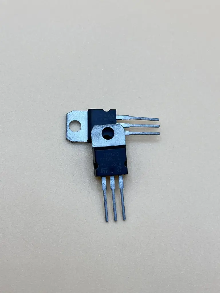
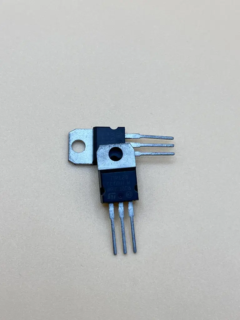


The TIP120 is a high-current, high-voltage Darlington transistor used for switching and amplification applications. It is part of the TIP series of transistors and is well-suited for driving motors, relays, and other high-power loads. The TIP120 features a high current gain and can handle significant power dissipation, making it ideal for use in various electronic circuits requiring robust switching performance.
Key Features:
- Darlington configuration for high current gain
- High current handling capability
- High voltage rating for reliable operation in demanding environments
- Built-in protection against thermal overload and overcurrent
- Suitable for use in switching and amplification applications
- Type: NPN Darlington Transistor
- Collector-Emitter Voltage (Vceo): 60V
- Collector-Base Voltage (Vcbo): 60V
- Emitter-Base Voltage (Vebo): 5V
- Collector Current (Ic): 5A (maximum)
- Power Dissipation (Pd): 65W (maximum)
- Current Gain (hFE): Typically 1000 to 2000 (at Ic = 4A)
- Gain-Bandwidth Product (fT): 2 MHz (typical)
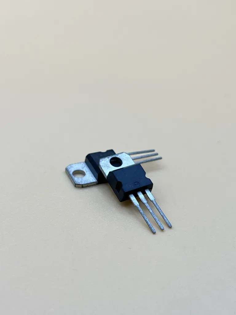
- Package Type: TO-220
- Motor and relay drivers
- High-power switching circuits
- Amplifiers
- Solenoid drivers
- Light dimmers and control systems
- Mount the TIP120 transistor on a suitable heatsink if high power dissipation is expected.
- Connect the base pin to the control signal through a base resistor to limit current.
- Connect the collector pin to the load and the emitter pin to ground.
- Ensure that the power supply and load are within the transistor’s ratings to avoid damage.
- Test the circuit to verify proper operation and adjust the base resistor as needed for the desired switching behavior.
- Ensure proper heatsinking to prevent thermal overload.
- Verify that the transistor’s voltage and current ratings are not exceeded in your application.
- Handle with care to avoid damage from static electricity or mechanical stress.
No Specifications